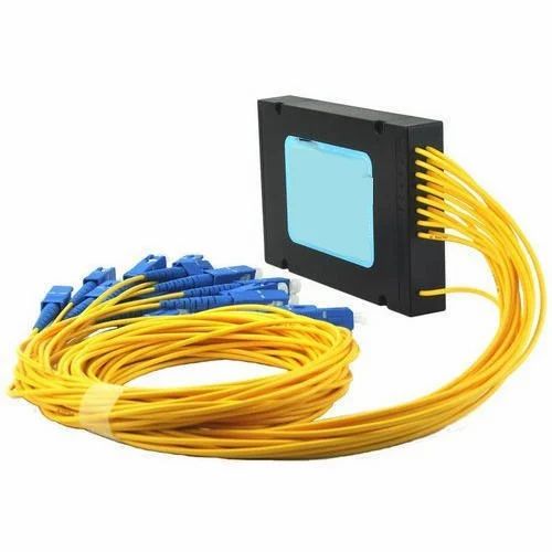

Draw the stated topology
Record the exact component reference and the number of input and output ports. The Fibre Optic Association describes a 1×N splitter as one input and N outputs, with other configurations also possible. Keep that topology separate from the number of active users or the whole network design. A photograph of a multi-fibre cable cannot establish its internal split ratio or connector specification.
Name the conditions and units
Retain the datasheet’s wavelength, connector and relevant specification conditions with its loss values. Ask whether a quoted figure concerns a particular path, excess loss or another stated measure. A unitless number cannot be compared responsibly with a loss specified in dB. Keep the actual document revision and component identifiers so a supplier’s answer remains traceable.
Separate ideal arithmetic from performance
An ideal equal split divides power between outputs. The ideal loss from splitting alone is 10 log10(N) dB: approximately 3.01 dB for two outputs and 6.02 dB for four. Actual components and connections can add loss and variation. These figures are mathematical examples, not manufacturer limits, a measured result or a complete optical power budget.
Ask for the actual engineering evidence
Compare the proposed component with the qualified design requirements and actual datasheet or test report. Leave missing conditions unresolved. This page does not teach field measurement, connector handling, network activation or instrument setup. Do not look into an optical connector or fibre. Use competent optical-network professionals and the appropriate safety procedures for real equipment.
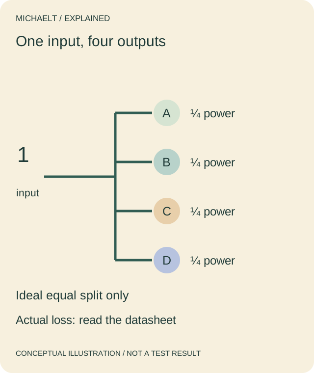
Read the drawing as text
An ideal equal 1×4 split has four quarter-power outputs and about 6.02 dB splitting loss. Actual component losses require specified evidence.
Work through an example
A fictional component is described as 1×4. The reviewer draws one input and four outputs, records 6.02 dB as the ideal equal-splitting loss only, and asks for the actual insertion-loss specification at the required wavelength. The mathematical result is not relabelled as a passed component test.
Illustrative example; figures, people and organisations in the worked record are fictional.
The example record
Topology
- Illustrative entry
- 1 input / 4 outputs
- Limit
- Not a complete network
Ideal split
- Illustrative entry
- 10 log10(4) ≈ 6.02 dB
- Limit
- Arithmetic only
Actual loss
- Illustrative entry
- Datasheet needed
- Limit
- Conditions must match
Decision
- Illustrative entry
- Qualified engineering review
- Limit
- No installation approval
Download blank worksheet (.csv) ↗Download worked example (.csv) ↗
Keep your own record
Use the result within its scope
Keep ideal calculations and measured specifications distinct. No component is tested, recommended or approved for a live network here.